
retrofit your fluorescent sign by first assessing the fixture condition, ballast type, sockets, and wiring, then choosing compatible LED tubes or module kits; remove tubes and ballasts, install drivers or direct-wire per manufacturer instructions, ensure proper heat dissipation and mounting, verify wiring and polarity, test uniform illumination, and confirm compliance with local codes.
Key Takeaways:
- Inspect the sign: document lamp sizes/count, internal space, ballast type, wiring, and condition of the face/diffuser before buying parts.
- Select the right LED solution: choose direct-fit tubes, ballast-compatible retrofit kits, or custom LED modules based on lumen output, color temperature, IP rating, and sign depth.
- Address electrical changes: remove or bypass fluorescent ballasts when required, install proper LED drivers, fusing and surge protection, and ensure wiring meets local electrical code.
- Ensure mechanical and thermal compatibility: confirm mounting/heatsinking, secure connectors, and provide ventilation or thermal paths to prevent overheating and maintain uniform illumination.
- Test and finalize: verify flicker-free operation, uniformity and dimming function, label the retrofit, dispose of fluorescent lamps per hazardous-waste rules, and obtain any required inspections/permits.
Understanding LED Retrofits
When you convert a fluorescent sign to LED, focus on physical constraints, diffusion, and electrical compatibility: sign depth often dictates whether you use slim linear modules or high-output COB strips, and typical LED retrofits cut fixture wattage by 50-70% while delivering 50,000-100,000 hours of service. Pay attention to thermal paths and driver selection-undersized heat sinks or improper drivers cause early lumen depreciation-so document lamp count, measured lumen output, and ambient temperature before ordering components.
Benefits of LED over Fluorescent
You gain measurable savings and performance: LEDs commonly reduce energy use by 50-70%, outlast fluorescents (50,000+ hours vs 10,000-15,000), improve CRI (80-90+), and eliminate warm-up or flicker issues. For example, replacing four 32W tubes (128W) with a 60W LED retrofit saves ~68W and cuts maintenance costs; rebates and lower HVAC load often shorten payback to 1-3 years depending on run hours.
Key Components of an LED Retrofit Sign
You’ll replace or add specific parts: LED modules or strips (SMD or COB), a compatible LED driver (constant current or voltage), heat sinks or thermally conductive channels, diffusers/lenses, wiring harnesses, connectors, mounting clips, gaskets for sealing, and surge protection. Also plan for a ballast bypass or removal when using direct-drive modules to avoid compatibility and reliability issues.
Digging deeper, specify driver and module specs: choose constant-current drivers sized to the string (350-700mA common) or 12/24V constant-voltage for strip systems, target 1,000-3,000 lm/ft depending on face uniformity, and pick color temperature (2700-6500K) and CRI for brand consistency. Require IP ratings (IP54-IP65) for outdoor faces, include a 6kV/3kA surge device where signage is exposed, and verify thermal resistance so junction temps stay below manufacturer limits for longevity.
Planning Your Retrofit Project
You should plan the scope by listing each sign, lamp count, trough depth, ballast type and access method; for example a storefront run of ten 4-ft, 2-lamp signs will need roughly 20 tubes and 3-5 hours of onsite work. Factor permit lead times (2-6 weeks), supplier lead (1-3 weeks for standard LED tubes, 3-6 weeks for custom modules), and staged rollouts to minimize downtime.
Assessing Existing Signage
You should open every cabinet and document lamp sizes, ballast labels (magnetic vs electronic), socket condition, wiring gauge, and throat depth; measure face translucence and any hot spots with a lux meter when possible. Note corroded frames or water intrusion since those often require enclosure repair first. For example, 8‑ft fixtures commonly need ballast bypass kits or replaced tombstones for single-ended LED tubes.
Budgeting and Timeline
You should estimate materials at $10-$30 per LED tube or $25-$100 per retrofit kit, plus labor at $50-$120/hour; include disposal fees ($5-$20 per ballast) and permit costs. Single-sign conversions typically take 1-3 hours; a 20-sign roll-out often finishes in 2-4 days of install plus 2-6 weeks for approvals and shipping. Target a 1-3 year payback assuming 50-70% energy savings and available rebates.
You should build a contingency of 10-20% for unexpected wiring, transformer replacements, or custom face work (custom acrylic faces often add 2-4 weeks and $200-$800 per sign). Example: 20 tubes × $20 = $400 materials, 4 hours labor × $80 = $320, add $100 disposal/permit → $820 total; at 60% savings on a 1,000W legacy setup running 12 hours/day you save ~216 kWh/month (~$26/month at $0.12/kWh), giving ~2.6 years simple payback.
Tools and Materials Needed
For a smooth retrofit you’ll want safety gear (gloves, goggles), a sturdy ladder, multimeter and non-contact voltage tester, insulated screwdrivers, wire strippers/crimpers, heat gun, cordless drill and rivet gun, plus sealants and silicone for weatherproofing. Bring a selection of screws, nylon zip ties, thermal tape, and replacement wiring (14-18 AWG). For a typical 4 ft sign plan on one 24 V, 60-100 W LED driver per 1-3 linear strips depending on layout.
Essential Tools for Installation
You should carry a multimeter (auto-ranging), non-contact voltage tester, insulated hand tools, and a quality wire stripper/crimper; these prevent miswires and speed splices. Add a heat gun for shrink tubing, a cordless drill with metal bits, rivet gun, and needle-nose pliers. Use an angle finder and tape measure for accurate module placement; a torque screwdriver helps get consistent screw pressure on terminal blocks.
Components and Supplies Overview
Choose LED modules or 12/24 V strips (2835/5050), matching constant-voltage drivers or constant-current drivers (350/700 mA) for individual modules, plus IP-rated connectors, quick-disconnects, and terminal blocks. Include aluminum mounting channels or strips for heat dissipation, diffusers, silicone gaskets for outdoor seals, and appropriate wire (mains 14-16 AWG, low-voltage 18-22 AWG). Expect LED efficacy of 100-150 lm/W when selecting modules.
Size drivers by totaling module wattage and adding ~20% margin: e.g., twenty 1.2 W modules = 24 W, so use a 30 W driver. For outdoor or high-ambient signs pick IP65 drivers and waterproof connectors; attach strips to aluminum channels or surfaces rated for thermal transfer to keep junction temperatures below ~60 °C. Use soldered joints or rated crimp connectors for reliability and seal with silicone where moisture could enter.
Step-by-Step Retrofit Process
Work through the conversion in clear stages so you can track parts and power. Start by isolating power and documenting lamp counts and wiring, then remove the fluorescent components, mount LED modules and driver(s), wire with attention to voltage and polarity, and finish with diffuser reinstallation, sealing, and a full photometric check (aim for uniformity ±15%). Typical retrofit for a 48″ trough takes 1-2 hours per sign once prepped.
Step-by-Step Overview
| Step | What you do |
|---|---|
| 1. Power & Document | Shut off mains, test with non-contact tester, photograph wiring and lamp layout (e.g., 2-lamp or 4-lamp trough). |
| 2. Disassemble | Remove face/diffuser, fluorescent tubes, ballast and tombstones; label wires and note ballast type (electronic/magnetic). |
| 3. Prepare Backplate | Clean and inspect metal backer; plan module spacing (2-4 in. typical) and driver mounting location. |
| 4. Mount LEDs | Attach modules or strips to metal using screws/thermal tape; ensure heat path to metal for thermal management. |
| 5. Wire & Driver | Select driver with 20-30% headroom (e.g., 24V DC, 30W for 20W load), run positive/negative in parallel, use appropriate gauge and fusing. |
| 6. Test & Adjust | Power up, measure voltage/current, check for flicker and uniformity, tweak spacing or add diffusing film if hotspots appear. |
| 7. Seal & Reassemble | Weatherproof entry, secure face/diffuser, add silicone sealant on outdoor signs, and record final measurements. |
Disassembling the Fluorescent Sign
You should cut power and verify zero voltage, then remove face/diffuser and fluorescent tubes using gloves to avoid glass breakage; photograph the ballast wiring and label each conductor (hot, neutral, ballast leads). Take out tombstones and the ballast-note ballast model numbers to know if you must rewire to bypass. Use a multimeter to confirm circuits are dead before touching wiring and keep parts organized for disposal or recycling.
Installing LED Modules and Wiring
Mount LED modules every 2-4 inches for even illumination; fasten to the metal backer with screws or 3M thermal tape, ensuring good thermal contact. Select a driver that matches input mains (120-277 VAC common) and output (12V/24V DC typical), size it at 20-30% above total LED wattage (e.g., 40 modules × 0.5W = 20W → 30W driver). Run DC leads in parallel, respect polarity, and use IP-rated connectors for outdoor signs.
Wire selection and layout matter: for 24V runs keep voltage drop under 3%-18 AWG is fine up to ~6 ft, 16 AWG for longer runs; calculate drop (Vdrop = I × R) and, if needed, split runs so each driver output feeds shorter branches. Add an inline fuse sized slightly above expected current (I = W/V), and mount the driver with ventilation away from direct weather. If using LED tubes that replace fluorescents, fully remove or bypass the ballast per manufacturer instructions and cap tombstones as required; always retest amperage and check for flicker for at least 15 minutes before sealing the sign.
Testing and Troubleshooting
After reassembly you should run a systematic test sequence and log results: power-up verification, 30-minute burn-in to stabilize temperatures, and functional checks of each module and the face. Use a checklist to note input voltages, driver outputs, ambient and case temperatures, and any flicker or color shift. If any reading falls outside the driver’s label (for example, output current 350-700 mA or max case temp 70°C), isolate that circuit for repair before final sealing.
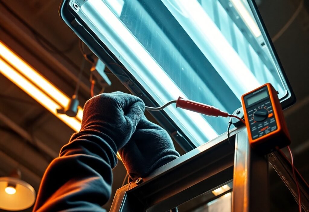
Electrical Testing Procedures
Confirm line voltage at the sign (120 V, 277 V, or as labeled) with a meter, then measure driver output (Vout and mA) under load-expect 24-48 VDC or constant current like 350/700 mA depending on the kit. Use a clamp meter to record input current and calculate power (P=V×I). Check continuity and ground resistance (<1 Ω typical). Run a 30-minute thermal test and ensure case temp stays below the driver's Tmax, often 60-70°C.
Common Issues and Solutions
Flicker, no-start, dimming inconsistencies, and overheating are the most frequent faults. Flicker often stems from incompatible dimmers or leftover ballast circuitry-remove the ballast or install a compatible 0-10 V/phase-cut driver. No-start can mean reversed polarity, open connections, or a failed driver; swap with a known-good driver to isolate. Overheating usually requires better thermal path or reduced drive current (e.g., change from 700 mA to 350 mA kits).
In one retail-channel retrofit, swapping a failed constant-current driver resolved intermittent shutoffs that occurred at 40 minutes; post-replacement current stabilized at 0.58 A and case temperature fell from 78°C to 62°C. For dimming problems, test with a simple non-dimming supply-if the issue disappears, fit a compatible dimming driver or correct the control wiring (verify 0-10 V control range and polarity). Document each step and retest after any repair.
Maintenance and Longevity
Routine upkeep dramatically extends life expectancy: LEDs typically run 50,000-100,000 hours versus 8,000-15,000 for fluorescents, and you can cut energy use 40-60% by converting-see Converting your Fluorescent Signage to LEDS. Clean faces every 6-12 months, inspect seals and vents seasonally, log driver temps and run hours, and plan driver/module replacement before visible lumen loss or color shift; many warranties run 5-10 years.
Caring for Your LED Retrofit Sign
You should clean the diffuser with a soft cloth and mild soap every 6-12 months and avoid ammonia-based cleaners that haze acrylic. Inspect wiring, gaskets, and fasteners quarterly, and measure driver output annually to catch thermal drift. If you note >10% lumen drop or color shift, swap the driver or modules; most retrofit kits allow module replacement in 10-30 minutes.
Upgrading Options for the Future
You can add 0-10V or DALI dimming and networked controls to gain another 20-30% energy savings and enable schedules or zoning. Swap to higher-CRI (≥90) modules for truer brand colors, choose tunable white (2700-6500K) for time-of-day adjustments, or upgrade to NTC-rated drivers for extreme temperatures and remote monitoring for fault alerts.
For scalability, pick modular kits with snap-in strips or panels so you can replace a module in 10-20 minutes and step lumen output from ~200 to 800 lm/ft as needs evolve. When you add networked dimming and monitoring across multiple locations, projects commonly see an extra 15-30% cut in energy and halve routine maintenance visits, lowering total cost of ownership over a 3-5 year window.
To wrap up
To wrap up, you complete an LED retrofit sign conversion from fluorescent by evaluating the existing fixture, selecting compatible LED modules and driver, removing tubes and ballasts, ensuring correct wiring and thermal management, testing lumen output and color, sealing for weather protection, and disposing of fluorescent components according to regulations to deliver a reliable, energy-efficient sign upgrade.
FAQ
Q: What are the overall steps to convert a fluorescent sign to LED?
A: Start by assessing the existing sign, enclosure, wiring, and available working space. Choose a retrofit method: ballast-bypass LED tubes, ballast-compatible LED tubes, LED strip modules with a remote driver, or complete LED module replacement. Remove or bypass the ballast if required by the chosen product, mount LED modules or strips to provide secure mechanical support and thermal path, install the correct LED driver (or confirm integrated-driver compatibility), rewire the sign to supply the driver with AC mains (hot, neutral, ground) using proper connectors and strain relief, replace or clean diffusers/reflectors to improve uniformity, seal and weatherproof outdoor signs, then test for voltage, polarity, lumen output, color consistency, flicker and switching/dimming behavior before relabeling and returning to service.
Q: Do I have to remove the fluorescent ballast and how should the sign be rewired?
A: Many LED retrofit solutions require removing the ballast (ballast bypass) because the LED driver must be fed directly from line voltage; others are designed to work with existing ballasts-check the product spec. For ballast bypass: de-energize the sign and lock out power, open the wiring compartment, disconnect and remove the ballast, cap off and properly dispose of the ballast per local regulations, then wire mains hot and neutral directly to the LED driver input (or to the tube holders if using single-ended tube conversions). Ensure tombstones are shunted or replaced appropriately when using direct-wired tubes. Connect equipment ground to the sign chassis and driver ground. Use properly sized conductors, strain reliefs, wire nuts or terminal blocks rated for the environment, and follow local electrical code; if unsure, use a licensed electrician.
Q: How do I choose the right LED modules and driver for sign retrofit projects?
A: Select LEDs with appropriate lumen density and beam spread for the sign depth and desired brightness, and choose a correlated color temperature (CCT) and color rendering index (CRI) that match the brand colors and surrounding lighting. Drivers should match the LED type: constant-current drivers for series LED modules, constant-voltage (12/24 VDC) drivers for parallel strip systems; confirm input voltage range (120-277 VAC common) and dimming protocol if required (0-10V, PWM, DALI). Specify IP-rated components for outdoor or damp installations, include surge protection for exposed locations, verify thermal limits and mounting for heat dissipation, and confirm UL/ETL listings or other applicable certifications for signage use.
Q: What techniques produce even illumination and consistent color across the sign face?
A: Use properly spaced LED modules or high-density strips so spacing-to-depth ratios yield uniform light; add reflectors or light-guiding panels behind the diffuser to spread light across deep cabinets. Replace aged or yellowed diffusers, clean inner surfaces, and consider frosted or spread-diffuser films to eliminate hot spots. Match LED bins for CCT and flux when using multiple reels or modules to avoid color shift, and test the sign at night from typical viewing distances to confirm uniformity. If hotspots persist, add internal baffles, adjust module angles, increase LED density, or change diffuser type rather than simply increasing lumen output.
Q: What testing, documentation, and maintenance should be done after completing the retrofit?
A: After installation, verify AC input voltage at the driver, measure driver output current or voltage to confirm LEDs are operating within spec, inspect for flicker and validate dimming/photocell operation where applicable. Measure lux or foot-candle levels and compare with target values, check for uniformity and color consistency, and perform a thermal check to ensure components stay within rated temperatures. Label the sign with new electrical ratings and driver info, save datasheets and wiring diagrams for future service, and dispose of fluorescent lamps and ballasts according to hazardous-waste rules. Schedule periodic inspections for moisture intrusion, wiring integrity, and lumen depreciation, and replace drivers or modules if performance degrades.